Fluid Filler Neck
A recurring customer came with a request for a fluid tank filler neck that wouldn’t corrode like their current metal solution. With a diagram for the top mounting surface hole spacing and dimensions for different sections of the neck, I was able to put toogether a specialized model that suited their needs better than any other commercially available options! Check out below for different steps and different stages of the process!
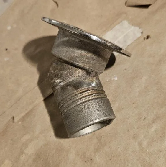
The image to the left was provided by the customer as an example of the rough shape that they were going for. The manufacturer’s website had dimensions for hole spacing for the top plate, which let me match the current mounting points.
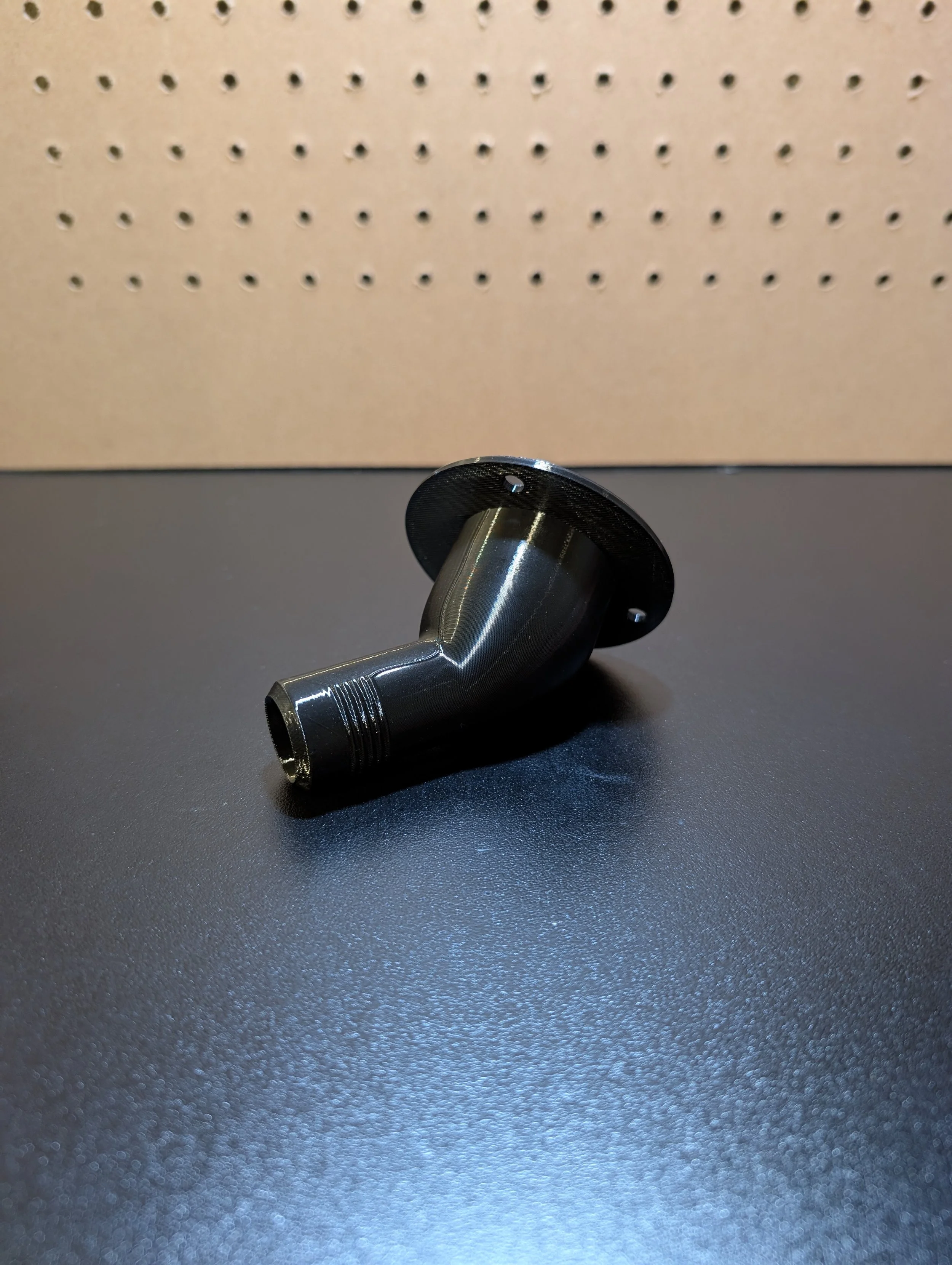
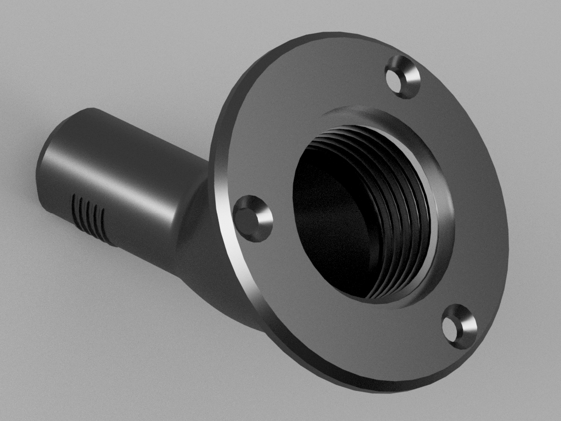
As a modification, the customer asked me to leave the diameter of the inlet immediately inside the opening, but to step down the 45 deg angled portion from 44mm to 25mm so a different hose could be used inside the tank.
I was able to maintain each dimension that the customer needed to remain the same (including the threaded cap design), while changing those that could be improved for his specific setup.
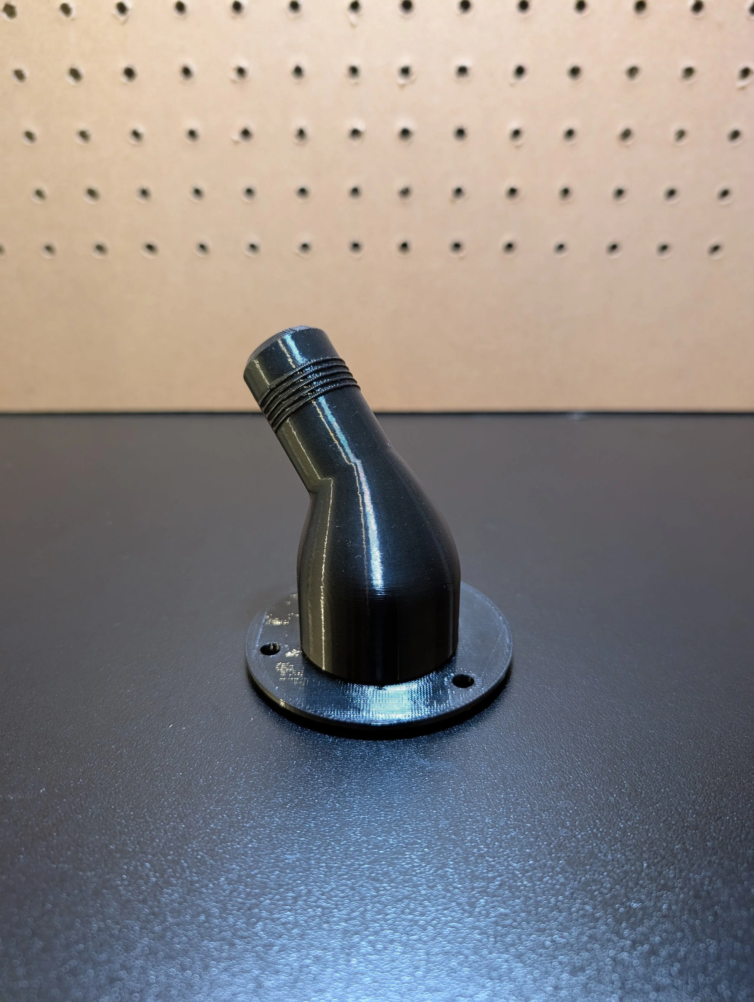
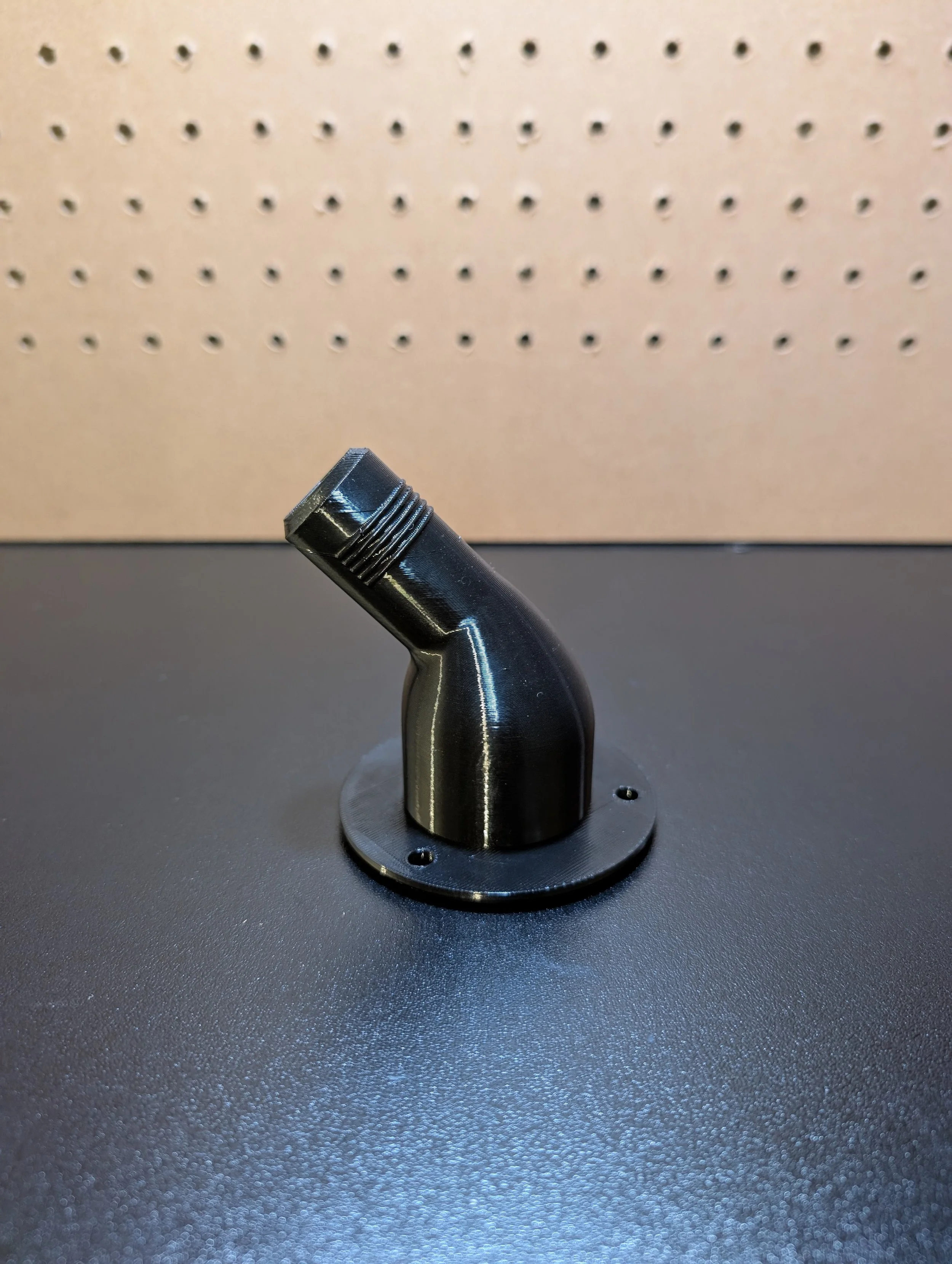
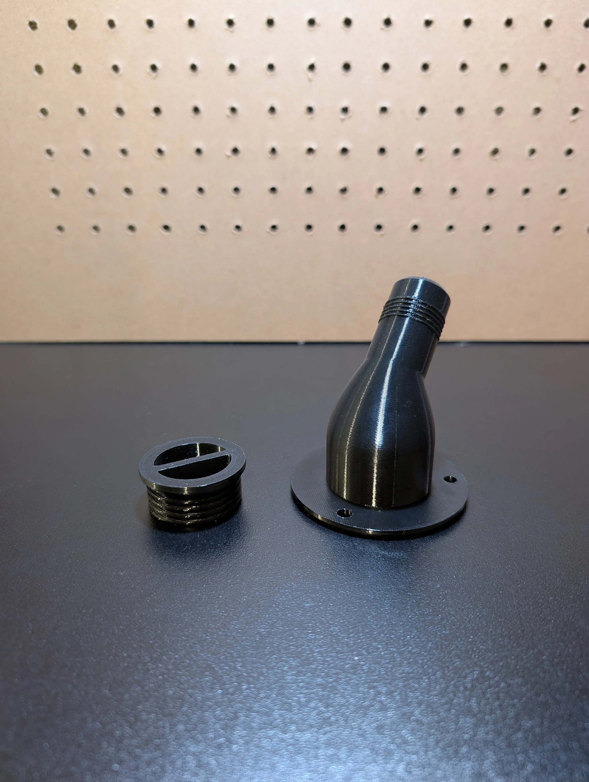
To the right and in the photo gallery below, is the final product, printed in PETG. To maximize print quality, ridges only spanned the top 120 degrees of the pipe surface.
After after setting the diamters, lengths, and positions of the two cylindrical sections of the part, they were lofted together to create a strong and smooth transition.
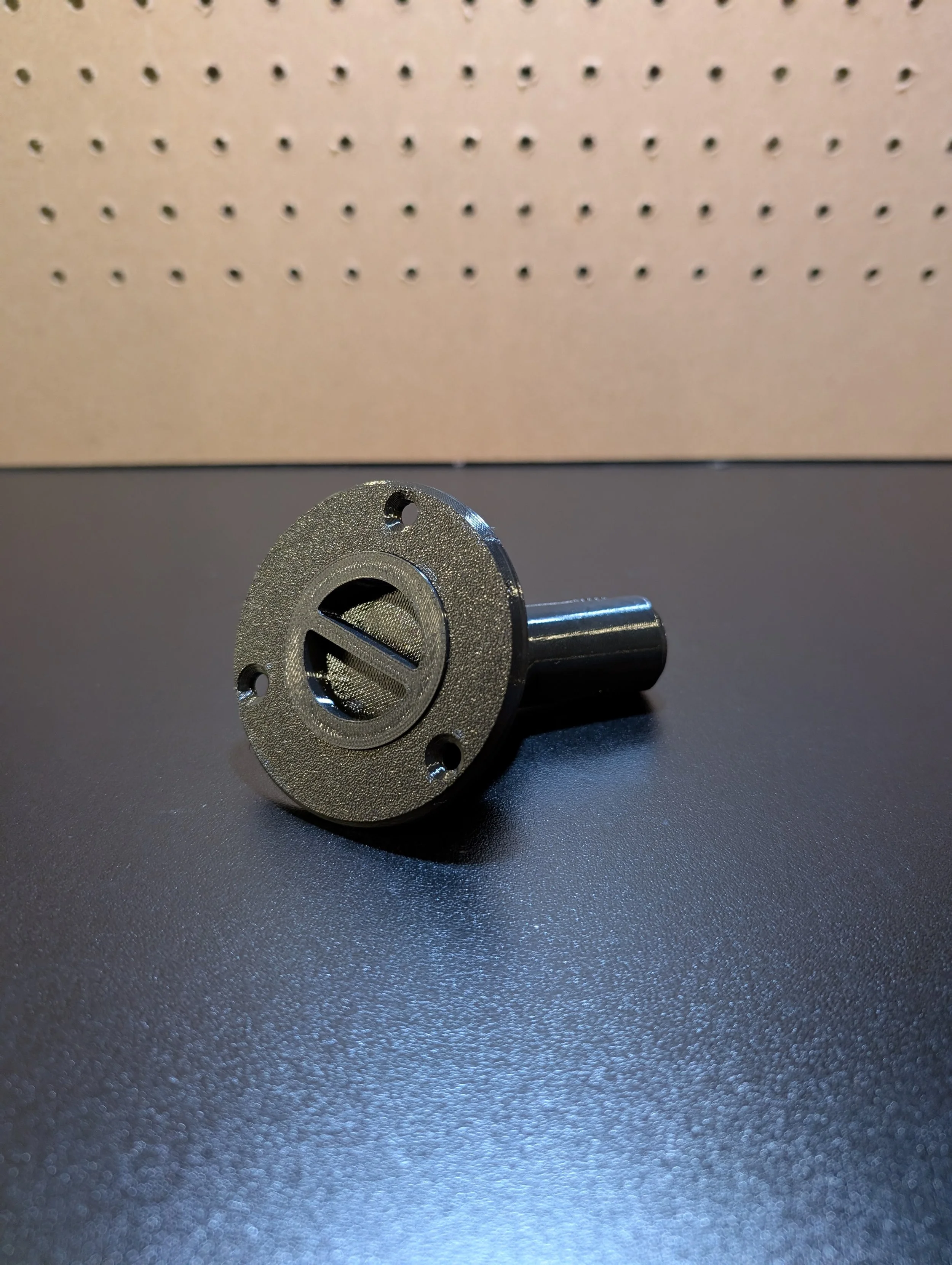
The cap for the filler neck interfaces with the neck itself via standard printed machine threads. By creating the threads and offsetting the surfaces a fraction of a mm inward, enough clearance is created for a simple and reliable closure mechanism.